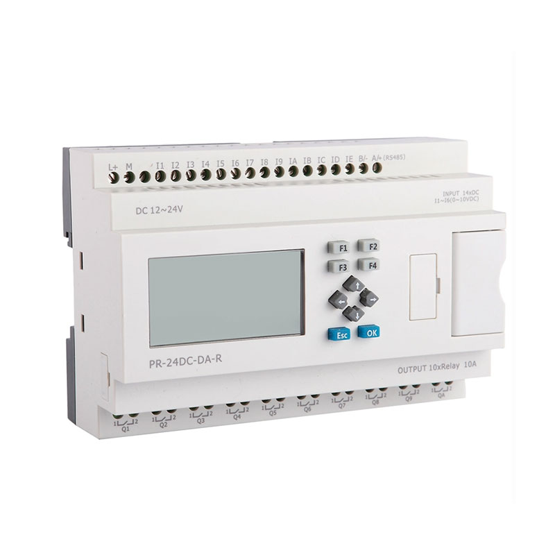
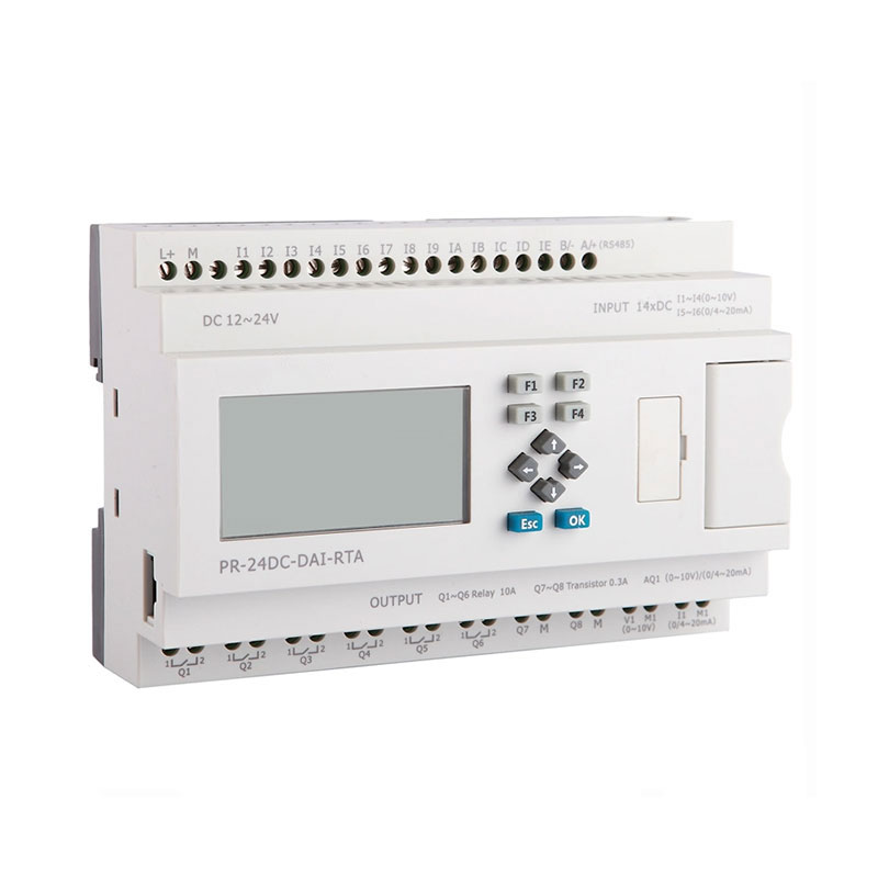
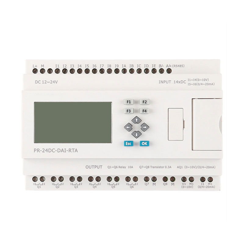
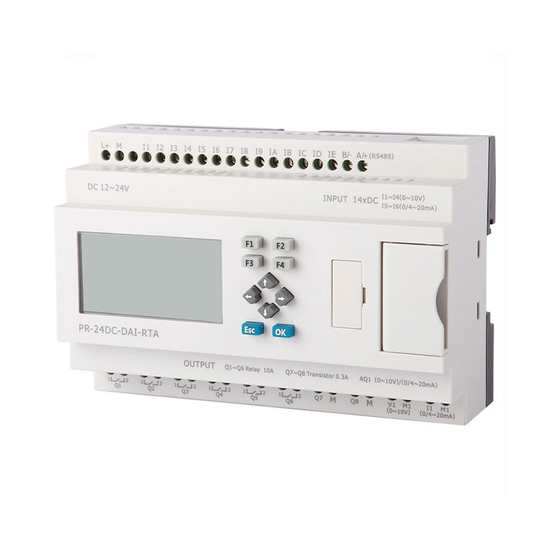
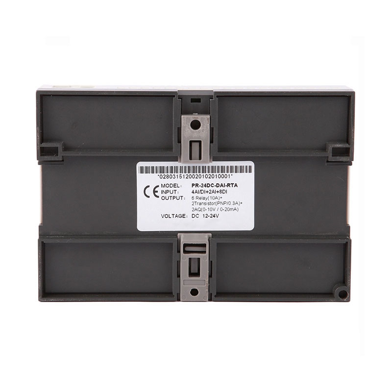
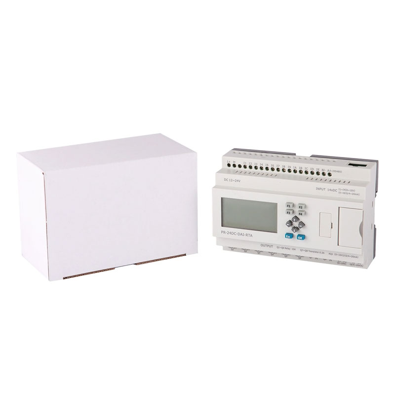
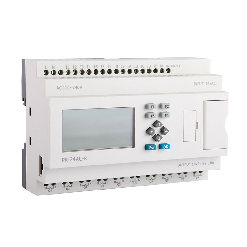
PR- 24 range(Micro PLC) is advanced level model, incorporating a good mix of digital and Analogue IO, Integrated High Speed inputs and PWM output,clock with calendar, counters , timers , integrated keypad display, serial communications and an expansion port. Available in 120V/240VAC or 12V/24VDC versions; Easy to configure with drag-and drop function blocks using FREE xLogicSoft software. Program capacity has been enlarged to 1024 function blocks as well, also high-speed count reaches 60KHZ.
Timers : 1024
Counters : 1024
Function Blocks : 1024
Operation temp. : -20℃-55℃
Storage :-40℃-70℃
Protection : IP20(Non-waterproof)
Micro PLC PR-24 series (Expandable Range)series overview:
PR-24 range offers 4-line*16 characters LCD display and keypad for program modification or display and control whilst program is running. An expansion port allows the connection of up to 16 expansion modules, extending the I/O channel count. Now it is also possible to use the analog output module to solve simple closed-loop control tasks.
Heating and cooling systems can be designed with the RTD PT100 module using special functions for PI control,ramp response and analog multiplexer.
Highlight of PR-24 Series
◆70 ready-to use functions integrated-no additional devices such as operating hours counter required.
◆Extremely large program capacity:up to 1024 functions possible.
◆12 digital inputs(incl 6AI with 12/24V DC)and 6 digital outputs on board.
◆Flexibly expandable up to 142DI,138DO,72AI,and 32AO.
◆Display of message texts,actual and set-point values and direct modification of the values on the display(not on pure variants).
◆Integrated data retentivity-ensures backup of the current values in the event of a power failure.
◆Customizable Start-up page/screen.
◆Bool function,multiple timers,counters,PWM,PI controller,Ramp.Analog math supported.
◆Can be modularly expanded up to 280 I/Os.
◆230V units can be expanded with analog modules.
◆Datalogging:Data from the production process can be saved in SD card of the external accessory called ELC-MEMORY to either read it with a PC or evaluate it from the SD card at the workstation.
◆Extremely simple software
◆Display of up to 128 messages.
◆Multiple kinds of registers can be accessed.
◆Parameters setting menu in LCD panel.
◆Parameters can be modified in the alarming message.
◆Modbus RTU/ASCII protocol supported.
◆Retentive memory capability.
◆Powerful communication capability(1RS232 port,2 RS485 ports(1built-in and 1 need RS485 extension) and 1 expansion port)
◆Password protection.
◆It’s optional for xLogic to act as salve or master in certain Modbus communication network.
◆Backup at Real Time Clock(RTC) at 25 ℃:20 days.
◆2 PWM channels optional.
◆Communicate with third party device which supports Modbus network.
Model:PR-24DC-DAI-RTA
GENERAL SPECIFICATIONS
Timers : 1024
Counters : 1024
Function Blocks : 1024
Operation temp. : -20℃-55℃
Storage :-40℃-70℃
Protection : IP20(Non-waterproof)
RTC accuracy : MAX ±2S/day
RTC Backup at 25 °C : 20 days
Program and settings Backup :10 years
Data Power-off retentivity : 10 years
Modify parameters via keypad LCD: yes
Dimensions : 95*90*55(Unit:mm)
Certificate : CE
Installation : 35mm-DIN rail or screw for installation
Expansion capacity: 16 modules (PR-E-16)
Password protection : 4-digit number password protection or disable program upload function
Communication interface : TTL interface , 1 RS232 port & 1 RS485 port
Communication protocol : Modbus RTU/ASCII
Technical Index
| Power supply: | ||
| Nominal voltage | DC 12-24V | |
| Operating limits | DC 10.8-28.8V | |
| Immunity from micro power cuts | Typ.5 ms | |
| Max. Startup current | Max. 0.25A | |
| Max. absorbed power | 3.5 W (10.8V dc) ; 4 W (28.8V dc) | |
| Protection against polarity inversions | Yes | |
| Input parameters: | ||
| Input No | 14 ( I1-IE ) | |
| Digital input | 12 ( I1-I4 )(I7-IE) | |
| Analogue input | 4 ( I1-I4)(0..10V DC) +2(I5-I6)(0...20mA) | |
| Digital inputs( I7-IE ) | ||
| Input voltage | DC0-28.8V | |
| Input signal0 | < 5V DC; <1mA | |
| Input signal1 | > 8 V DC;>1.7mA | |
| Input current | 2.3mA @ 10.8V dc 2.6mA @ 12.0 V dc 5.2 mA @ 24 V dc 6.3 mA @ 28.8 V dc |
|
| Response time | 0 to 1 :<1 ms ;1 to 0 :<1 ms | |
| Maximum counting frequency | 60k Hz(I9--IC) | |
| Sensor type | Contact or 3-wire PNP | |
| Input type | Resistive | |
| Isolation between power supply and inputs | None | |
| Isolation between inputs | None | |
| Inputs used as digital inputs( I1-I4 ) | ||
| Input voltage | DC0-28.8V | |
| Input signal0 | < 5V DC;<0.1mA | |
| Input signal1 | > 8 V DC;>0.3mA | |
| Input current | 0.4mA @ 10.8V dc 0.5mA @ 12.0 V dc 1.2mA @ 24 V dc 1.5mA @ 28.8 V dc |
|
| Response time | 0 to 1 :Typ. 1.5 ms ;1 to 0 :Typ. 1.5 ms | |
| Maximum counting frequency | Typ.:4 HZ | |
| Sensor type | Contact or 3-wire PNP | |
| Input type | Resistive | |
| Isolation between power supply and inputs | None | |
| Isolation between inputs | None | |
| Inputs used as analog inputs( I1-I4 ) | ||
| Measurement range | DC 0---10V | |
| Input impedance | Min, 24KΩ ; Max. 72KΩ | |
| Input voltage | 28.8 V DC max | |
| Resolution | 10bit ,0.01V | |
| Accuracy at 25 °C | ± (Max.0.02)V | |
| Accuracy at 55 °C | ± (Max.0.04)V | |
| Isolation between analog channel and power supply | None | |
| Cable length | 10 m max. shielded and twisted | |
| Current Input parameters(I5-I6) | ||
| Input No | 2(I5-I6) | |
| Digital input | None | |
| Analogue input | 2 (I5-I6) | |
| Analogue signal | 0/4….20mA current | |
| Resolution | 0.02mA | |
| Accuracy at 25 °C | 0.05mA | |
| Cycle time for analog value generation | Typ. 50 ms | |
| Output parameters: | ||
| Output No. | (Q1-Q8,AQ1) | |
| Output type | Q1-Q6(Relay)+ Q7-Q8(Transistor),AQ1(0-10V)/(0/4-20mA) output | |
| Relay output(Q1-Q6) | ||
| Continuous current | Resistive load 10A/Inductive load 2A | |
| Max. breaking voltage | AC 250 V DC 110 V |
|
| Max. Allowable Power Force | 1250VA 300W |
|
| Electrical durability Expectancy | 105 Operations at Rated Resistive Load | |
| Mechanical life | 107 Operations at No Load condition | |
| Response time | Operate Time : 15 mSec. Max. Release Time : 10 mSec. Max. |
|
| Built-in protections | Against short-circuits: None Against overvoltages and overloads: None |
|
| Transistor output(Q7-Q8) | ||
| Output No. | 2(Q7-Q8) | |
| Output type | Transistor(PNP) | |
| Breaking voltage | DC 5--30V | |
| Nominal voltage | ≤ Supply voltage | |
| Nominal current | Max. 0.3 A per channel | |
| Max. breaking current | 0.65 A | |
| Voltage drop | < 2 V for I = 0.3 A (at state 1) | |
| Response time | Make ≤ 1 ms Release ≤ 1 ms |
|
| Frequency (Hz) | resistive load : 10 Hz inductive load : 0.5 Hz |
|
| Built-in protections | Against overloads and short-circuits: No Against overvoltages (*): No |
|
| Galvanic isolation | None | |
| PWM frequency | 10K HZ | |
| PWM cyclic ratio | 0 to 100 % | |
| PWM accuracy at 120Hz | < 0.5 % (20 % ➞ 80 %) load at 10 mA | |
| Max. Breaking current PWM | 50 mA | |
| Max. cable length PWM | 20m | |
| Analog output(0...10V): | ||
| Output No | 1 AQ1 | |
| Output signal | DC 0…10V | |
| Internal value and signal relationship | AQ1(0..1000)= V1(0...10V) | |
| Resolution | 0.01V | |
| Accuracy at 25 °C | 0.02V | |
| Analog output(0...20mA): | ||
| Output No | 1 AQ1 | |
| Output signal | 0..20mA | |
| Internal value and signal relationship | AQ1(0...1000)= I1(0...20mA) | |
| Resolution | 0.02mA | |
| Accuracy at 25 °C | 0.05mA | |
| Relay Switch frequency: | ||
| Mechanism | 10Hz | |
| Resistor/light load | 2Hz | |
| Sensitive load | 0.5Hz | |
| Other parameters: | ||
| Weight | Approx.500g | |
| Program language | FBD & Ladder | |
| PR-24 Series CPU | ||||||||
| Model | Supply volt | Inputs | Outputs | High-speed count | PWM | HMI | RTC | G.W(g) |
| PR-24AC-R | AC110~240V | 14 Digital | 10relays(10A) | None | NO | YES | YES | 400g |
| PR-24DC-DA-R | DC12V-DC24V | 6 digital/(0-10V) +8 digital |
10 relays(10A) | 4 routes | NO | YES | YES | 400g |
| PR-24DC-DAI-RTA | DC12V-DC24V | 4 digital/(0-10V) 2(0/4 - 20mA)+8 digital |
6relay(10A)+2Transistor(0.3A)+1(0..10V)/ 1(0..20mA) |
4 routes | YES | YES | YES | 400g |
Installation Dimensions

Wiring Diagram

